Amplifone Reproduction Deflection Board Assembly Guide By Dezbaz
Created 01-Apr-2013, Edited 01-Oct-2022
1. For PCBs purchased from Amazing Arcading
2. Purchase other gear needed to complete the Project
Electronic Parts
![]() See
List
See
List
Posistor/PTC (for Degauss) (From a TV or eBay)
Harness Assembly Repro by Joeycuda on KLOV
Heatsink:
At present there are 3 options for the heatsink
Jaycar Heatsink
![]() and metal plate
and metal plate
![]() (We have a few on the website,
Amazing Arcading)
(We have a few on the website,
Amazing Arcading)
Repro Heatsink, more like the original, and ready to use (From Takeman on KLOV)
Original Heatsink
![]() You
may need to drill 4 holes for 2 x extra Resistors (TO-220 case)
You
may need to drill 4 holes for 2 x extra Resistors (TO-220 case)
![]()
Paint the heatsink if applicable, allow time to dry. Primer is recommended, then satin black paint.
EDIT: I found out later that it is better to not paint the flat area that makes contact with the transistors. Leave it bare alum.
Attach the Heatsink to the PCB. (Leave the screws loose, until the 6 x TO-220 parts are attached to the Heatsink)
There are 2 methods of attachment:
1. The inner holes of the Takeman repro are tapped, so you need 5/32" Screws x 2 (Approx 1/2" long)
2. The outer mounting holes are drilled to 4.1mm. So use either Qty 2 x 4mm Screws, Nuts & washers, or Qty 2 x 5/32" Screws, Nuts & washers
Once the heatsink is attached fit the 6 x TO-220 components first (Important points below)
NOTE: Fit Ferrites on the B (base) leg of Q4 and Q14 (Outer Transistors, LH Leg)
Look closely at the insulators on the pic above and below, see the insulators on the 4 outer Transistors. You can't see it but there are screw head insulators also (see lower pic)
Also, note the ferrite on Q4 and Q14 base legs (optional)
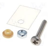
There are insulators between the 4 x Transistors (Outer '3 legged' items), and the Metal. Also, there is a circular insulator under the head of the screws.
See pic below

There are no insulators on the inner 2 x Resistors, because the Resistors are internally isolated to the tab
Secure all mounting screws and Component screws at this point
Once all 6 items are done up, set your ohmmeter to the lowest scale IE: 200, or the buzzer. There should be no connection/continuity between the flat of the transistors and the heatsink.
If there is continuity between the transistor and heatsink, try again, ensure there is an open circuit before proceeding to the next step.
Heat Paste is not needed on the 6 items mounted so far
Mount the 4 x TO-3 Transistors, Use a flat insulator & heat paste
* * * These DO NOT use a round insulator under the screw head on the Large TO-3 Transistors * * * *
WHY?? . . . If you look under the board you see the pads which make contact with the screws. So the screws complete the path to the metal surface of the Transistor
You still have to use the diamond shaped insulator, as the Transistor can't touch the Heatsink. The screws can't touch the heatsink either.
Using heatshrink, or tubing, insulate your mounting screws thread, not the screw head, as mentioned before. The screws pass through the heatsink. Use your buzzer to make sure the heatsink is not touching the components or screws.
* * If you have this right so far, Great! That is the hardest part of the whole Project
Next assemble all the resistors, zener diodes, diodes, capacitors, transistors, connectors and wiring
The orientation of the connectors are vital. Heavy failure can occur if you get them wrong
Please ensure zener diodes are correct polarity, and are in fact, zener diodes
Regular diodes polarity is important
Look at the ID on every Diode. Use a magnifier to get it right
Electrolytic caps are also polarity sensitive. The board is marked +, the cap is only marked -. That means you are actually matching in an opposite fashion.
So align the neg of the capacitor to hole in the board opposite to the positive etc
Transistors: Get them right, bend the leads so they fit in the same alignment as the picture ID on the board
Do the PNP ones first coz there are less. Double check they are all in.
Then the remaining should be NPN.
Look at the ID on every Transistor. Use a magnifier to get it right
You can use the 2 x Harness connectors for your board harness, or solder directly like the original
The removable harness was a convenience thing for the early days. So guys could order from an experienced harness maker. That option is long past in 2019. Maybe ask for another run if reading this after 2019
Need to ask for more info? email us